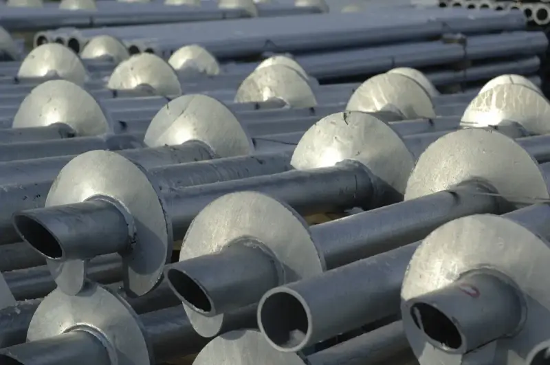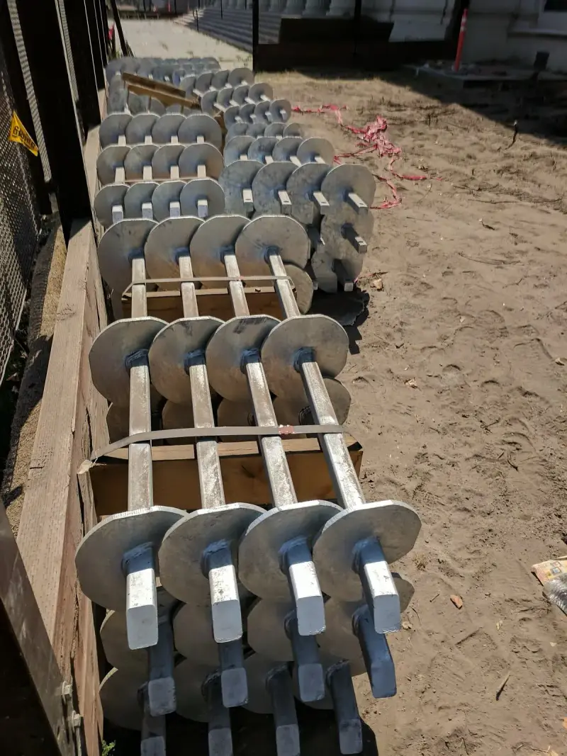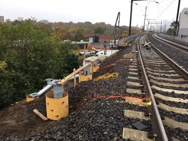
A helical pier foundation system has five working parts. There’s a lead section with helix plates that does the bearing, extension sections bolted on to reach depth, couplings that join them, a cap on top, and the concrete cap or grade beam the cap is cast into. Each part has its own rules in the building code or in the product’s evaluation report, and the system is only as strong as its weakest link.
If you’re building a new house, addition or commercial pad on piers, you’ll see these parts named on the pile schedule and in the submittals. Here’s what each one does.
The parts of a helical pier system at a glance
The dimensions below come from one manufacturer’s ICC-ES evaluation report, ESR-2794, which covers the Chance product line under the 2009 through 2024 editions of the IBC and IRC. Other brands have their own reports with their own sizes, so treat these as a worked example.
| Part | What it is | Example sizes (ESR-2794) | What governs it |
|---|---|---|---|
| Lead section | First shaft into the ground, with helix plates welded on | Up to three helices on the 1.5 in square shaft, up to four on the others | The product’s ESR and the engineer’s pile schedule |
| Helix plates | Round, spiral steel bearing plates | 8, 10, 12 or 14 in diameter; 3/8 or 1/2 in thick; 3 in pitch | AC358 geometry limits for torque correlation |
| Extensions | Plain shaft sections (some with helices) added to go deeper | Same shaft as the lead | Termination criteria on the pile schedule |
| Couplings | Bolted joints between sections | One 3/4 in bolt on the 1.5 in square shaft; two 3/4 in bolts on 2-7/8 in round | ESR coupling capacity |
| New-construction cap | Steel plate and sleeve that sits on the shaft top | 1/2 in thick, 6 in square plate on a 2-1/2 in sleeve for the 1.5 in square shaft | ESR embedment and tension rules |
| Concrete cap or grade beam | Reinforced concrete the piles are embedded in | Per the structural drawings | IBC 1810.3.11 |
Lead sections and helix plates: where the load goes into the ground
The lead section is the business end. Its helix plates are what actually bear on the soil, so the soils report decides where they need to end up.
ESR-2794 describes each helix as a circular steel plate, split from the center to the edge and formed into a clockwise downward spiral with a 3-inch nominal pitch. The plates are fillet-welded to the shaft. That 3-inch pitch matters because the pile is meant to advance about one pitch per turn, like a wood screw pulling into a board.
ICC-ES AC358, the acceptance criteria every helical pile evaluation report is written against, sets the conditions under which its default torque-to-capacity numbers apply. A few of them:
- helix diameters between 8 and 14 inches, 3/8 to 1/2 inch thick
- helix spacing along the shaft of 2.4 to 3.6 times the helix diameter
- a pitch of 3 inches, plus or minus 1/4 inch, the same on every plate
- the smallest helix at the bottom, with progressively larger plates above it
- the shaft advancing at least 85% of the pitch per revolution when final torque is read
Several helices give more bearing area at depth than one, and the trailing plates follow the path the lead plate cut. The engineer picks the count and diameters to suit the load and the soil.
Square shaft or round shaft?
You’ll see both on pile schedules. In ESR-2794 the square shafts are solid steel bars, 1-1/2 inch or 1-3/4 inch, and the round shafts are hollow structural tubes from 2-7/8 inch up to 4-1/2 inch outside diameter.
They don’t convert torque to capacity at the same rate. AC358’s default capacity-to-torque ratio (Kt) is 10 per foot for 1.5 and 1.75 inch square shafts, 9 for 2.875 inch round, 8 for 3.0 inch round and 7 for 3.5 inch round. A higher Kt means more rated capacity for each foot-pound of installing torque. Manufacturers can prove other values by testing, which is why the ESR for your product is the document to read.
The report also lists a combo pile: a 1-3/4 inch square lead with 3-1/2 inch round extensions, joined by a transition adapter. Which shaft fits your job is the engineer’s call, based on the loads and the soil profile.
Extensions and couplings: how the pile gets deeper
Nobody knows a helical pile’s exact final depth until it’s installed. ESR-2794’s installation steps spell out the routine: add extensions until the prescribed torque and depth are met and the shaft top is at or above the required elevation, then cut the shaft off at that elevation.
Couplings deserve as much attention as the helices. Under the IBC, a helical pile’s allowable load is half its ultimate capacity, and the ultimate is the least of several values. Those include the soil capacity, the torque-correlated capacity, any load test result, and the structural capacity of the shaft, couplings and helix plates (Section 1810.3.3.1.9). A coupling can govern.
In ESR-2794, square-shaft extensions have an upset socket that slips over the shaft below, held by a single through-bolt (3/4 inch on the 1.5 inch shaft, 7/8 inch on the 1.75 inch shaft). Round-shaft extensions use a sleeve coupler and two bolts. Every bolt the report calls for has to be in the joint.
The new-construction cap: where the steel meets the concrete
ESR-2794 separates two bracket families. Side-load brackets are made to bolt onto foundations that already exist, and they carry compression only. New-construction pile caps are direct-load brackets, a cap plate welded to a steel sleeve that slides over the top of the shaft, and they’re rated for both compression and tension. On a new build, the second kind is what goes on.
A cap only does its job once concrete is cast around it, and the report sets rules for that pour:
- the center of the shaft must be at least 6 inches from the end or corner of the footing or grade beam
- for a fixed-head condition, or any pile that resists tension, the shaft has to be embedded at least 7.5 inches into the footing or grade beam
- where the pile resists tension, the cap gets through-bolted to the shaft, and the design professional sets the cap embedment and the reinforcing needed to carry the uplift
The building code adds its own floor. IBC 1810.3.11 requires pile caps to be reinforced concrete, counts grade beams as pile caps, embeds the tops of deep foundation elements at least 3 inches into the cap, and extends the cap at least 4 inches beyond the edges of the elements. It also says the soil right under a pile cap isn’t counted on to carry vertical load, so the piles carry all of it.
The concrete on top, and why Colorado adds a gap
The last part of the system is the concrete pile cap or grade beam. Your concrete contractor forms and pours it. The pile installer’s work ends at the cut-off elevation and the seated cap.
On the Front Range the concrete detail often includes a void under the grade beam. The Colorado Geological Survey says expansive clay can push on foundations with pressures of 20,000 pounds per square foot or more. A grade beam sitting directly on that clay can get lifted. With a void form underneath, the beam spans from pile to pile and the clay has room to swell without bearing against it. The same swelling soil can grab the pile shaft and try to lift it, which is one reason Front Range piles are often designed for tension as well as compression. The caps and beams also have to respect the local frost depth; Denver’s residential code lists 36 inches.
Our article comparing helical piers and concrete footings covers when a pier system beats a conventional footing on Colorado soil.
How the load travels through the system
Trace the house weight down through the parts:
- Walls and floors bear on the grade beam.
- The grade beam spans to each pile cap, embedded at the depths the code and ESR require.
- The cap plate bears on the top of the shaft.
- The shaft carries the load down through each bolted coupling.
- The helix plates push it into the bearing soil the soils report identified.
In tension, as with wind uplift or swelling clay, the same path runs in reverse. Then the cap’s through-bolt and the coupling bolts are carrying the load as well as the helix plates. That’s why a missing bolt or a cap with too little embedment matters as much as a pile that stopped short of torque.
IBC 1810.4.11 adds one installation rule that protects the steel: installers can’t exceed the manufacturer’s rated maximum installation torque. Over-torquing a shaft to “make” capacity can damage the very parts you’re relying on.
What to check when the piles show up on site
- The shaft model on the pallet matches the pile schedule and the ESR named in the submittal.
- Helix count and diameters on the lead sections match the schedule.
- There are enough extensions on site for a reasonable depth range, plus coupling bolts and nuts for every joint.
- The new-construction caps match the shaft model, and the coating matches the submittal (in ESR-2794 a “G” at the end of a cap’s part number means hot-dip galvanized).
- The torque indicator has been calibrated within the previous 12 months, which ESR-2794 requires.
- Someone has the installation log ready to record depth and final torque for each pile.
For how the installation itself runs on a residential lot, see how helical pile installation works.
Planning a new build on helical piers?
Site Safe Helical Piers installs helical pier foundation systems for new homes, additions, decks and commercial projects across Denver and the Colorado Front Range. We work from your engineer’s pile schedule, record depth and torque for every pile, and leave the caps set at elevation for your concrete crew. Have a look at our services or send us your plans, or call 970-673-5615.