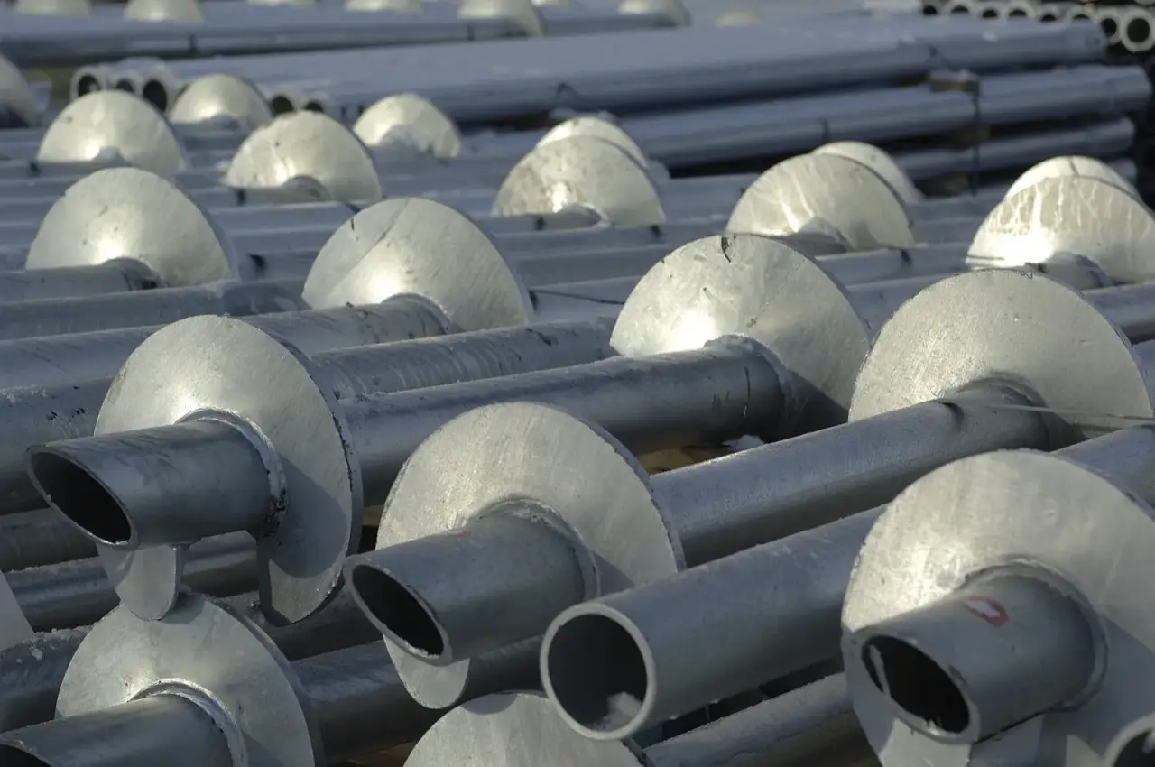
Helical pile capacity is the load a pile can safely carry, and under the building code it’s the weakest of four things: the soil around the helix plates, the steel shaft, the couplings that join shaft sections, and the helix plates themselves. Take that weakest number, divide it by two, and you have the allowable load. In the field, the soil part is usually checked by installation torque, because the harder a pile is to turn, the more it can hold.
Manufacturer charts show the steel side. Magnum Piering’s product listing, for example, runs from 9 to 22 tons allowable for a 3 inch round shaft up to 205 tons for a 10 inch shaft. Those numbers are real, but a pile only reaches its chart rating if the ground it’s screwed into can carry that much. This article explains how the two halves meet.
What the code says sets capacity
Section 1810.3.3.1.9 of the building code (Denver enforces the 2024 IBC with local amendments) says the allowable axial load of a helical pile is half of the ultimate capacity, and the ultimate capacity is the least of:
- The base capacity plus shaft resistance: the area of the helix plates times the ultimate bearing capacity of the soil or rock they sit in, plus friction on the shaft above the top helix.
- The ultimate capacity from well-documented correlations with installation torque.
- The ultimate capacity from load tests, where Section 1810.3.3.1.2 requires them.
- The ultimate axial capacity of the pile shaft.
- The ultimate axial capacity of the shaft couplings.
- The sum of the ultimate capacities of the helix plates.
Items 4 through 6 come from the manufacturer’s evaluation report and don’t change from site to site. Items 1 through 3 are about the ground, and they’re where the engineer and the installer earn their money.
How torque turns into capacity
As the pile advances, the drive head has to work harder in denser soil. The torque at the end of installation reflects the strength of the soil the helixes finished in. ICC-ES acceptance criteria AC358, the document manufacturers are evaluated against, writes it as a simple equation:
Ultimate capacity (Q) = Kt x final installation torque (T)
Kt is the capacity-to-torque ratio, and it gets smaller as the shaft gets bigger. AC358 Section 3.13.1 gives default values for conforming systems:
| Shaft size | Default Kt (per ft) |
|---|---|
| 1.5 in and 1.75 in square | 10 |
| 2.875 in OD round | 9 |
| 3.0 in OD round | 8 |
| 3.5 in OD round | 7 |
Manufacturers can prove other values with full-scale load tests, and their evaluation reports list the numbers that apply to their product. AC358 then sets the allowable capacity at half the ultimate (Q × 0.5), which matches the code’s factor of safety of 2.
Here’s where some explanations go wrong. Mascore’s torque article gives a 40,000 lb example with Kt = 8 and says you’d need roughly 5,000 ft-lb. That’s correct if 40,000 lb is the ultimate capacity. If 40,000 lb is the design load, the target torque doubles. Always ask which number you’re looking at.
Worked examples
A deck pile. Say a deck post carries about 2,500 lb. The ultimate capacity needed is twice that, 5,000 lb. On a 1.5 inch square shaft with Kt = 10, the target final torque is 5,000 ÷ 10 = 500 ft-lb. That’s a modest number, which is why deck piles go in quickly with small equipment.
A house pile. Say a pile under a new home carries 20,000 lb (10 kips) at the design load. Ultimate needed: 40,000 lb.
| Shaft | Kt | Target final torque |
|---|---|---|
| 2.875 in round | 9 | about 4,450 ft-lb |
| 3.5 in round | 7 | about 5,700 ft-lb |
The larger shaft has a lower Kt, so it needs more torque for the same capacity. That’s also why the drive head has to be sized for the job. And there’s a ceiling: IBC 1810.4.11 says installation torque must not exceed the manufacturer’s rated maximum for that pile. If a pile hits its torque limit before reaching the design depth, the engineer decides what happens next, which might mean a bigger shaft, different helixes or pre-drilling.
These examples show the arithmetic only. Real pile loads come from the structural engineer’s design, and real Kt values come from the evaluation report for the specific product.
When load tests come in
Torque is an indirect measure. A load test is a direct one. Under IBC 1810.3.3.1.2, load tests are required when the design load for a deep foundation element is in doubt, among other triggers, and the allowable load can’t be more than half the ultimate capacity the test shows. The building official can waive testing where it isn’t needed. Many residential projects rely on the torque correlation instead; your building department and engineer decide.
Larger commercial projects often run tests anyway, to confirm or sharpen the Kt value for the site. AC358 references the ASTM methods: D1143 for static axial compression and D3689 for static axial tension, with D3966 for lateral load. In AC358’s own test procedure, ultimate capacity is the load where the pile plunges or where net movement reaches 10 percent of the average helix diameter, whichever comes first. For a 12 inch helix that’s 1.2 inches of net movement.
Lateral load is handled separately. IBC 1810.3.3.2 allows no more than half the load that produces 1 inch of lateral movement at the top of the element or the ground surface, unless it can be shown that more movement won’t hurt the structure.
How to read an installation log
On commercial work in Denver, helical pile installation gets continuous special inspection under IBC 1705.9, and the inspector records the equipment used, pile dimensions, tip elevations, final depth and final installation torque. A good residential installer keeps the same log even when nobody requires it. A log line usually looks something like this:
| Field | What it tells you |
|---|---|
| Pile ID | Matches the pile location plan, so you can find any pile on the drawings |
| Shaft and helix configuration | Confirms the product the engineer specified went in |
| Lead and extension lengths | Adds up to the total length installed |
| Final depth / tip elevation | Shows the helixes reached the minimum depth the engineer set |
| Torque at each foot, or the last few feet | Shows whether torque was rising steadily as the pile reached firm soil |
| Final torque | Compared with the target from Kt and the design load |
| Pressure gauge or torque sensor ID | Ties the reading to a calibrated instrument |
| Date, operator, remarks | Notes on refusal, obstructions or anything unusual |
What to look for: every pile at or above the target torque, every pile at or below the minimum depth, and no pile where torque spiked once and then dropped (often a cobble or a buried object, not a bearing layer). A pile that reaches torque far shallower than its neighbors deserves a question.
Why Colorado clay changes the reading
On the Front Range, torque alone isn’t enough. Dry, stiff clay near the surface can turn a pile hard and give a big torque reading at a shallow depth. But that clay is in the active zone, the layer that swells and shrinks with seasonal moisture. The Colorado Geological Survey’s long-standing guidance for deep foundations on swelling soil is to put the bearing end well below the zone of seasonal moisture change and anchor it in non-swelling soil so it can’t be lifted.
So a Colorado pile design normally sets both a minimum depth (from the soils report’s active zone) and a minimum torque. The pile must meet both. Torque gained inside the active zone doesn’t count, because next spring that soil may be wet, soft and pushing upward.
Corrosion is the other site-specific check. AC358 puts soils with resistivity below 1,000 ohm-cm, pH below 5.5, sulfates above 1,000 ppm, high organic content, landfill or mine waste outside the scope of a standard evaluation. Your soils report should say whether any of those apply.
Questions to ask about capacity
- What’s the design load per pile, and is the quoted capacity allowable or ultimate?
- Which product, and what Kt does its evaluation report list?
- What final torque and minimum depth will each pile be installed to?
- Will I get the installation log for every pile?
- Is a load test required on this project, and who runs it?
Talk to us about pile capacity
Site Safe Helical Piers installs helical piles for new homes, additions, decks and commercial projects across Denver and the Colorado Front Range, and we log torque and depth on every pile. Send us your structural drawings or soils report and we’ll talk through pile size and torque targets with you and your engineer. Call 970-673-5615 or use our contact page. For more, see how helical pier installation works, why geotechnical testing matters, or our services.